Buyer Guide · commercial intent
Silicone Engine Mount OEM Manufacturing Guide
 Buyer Guide
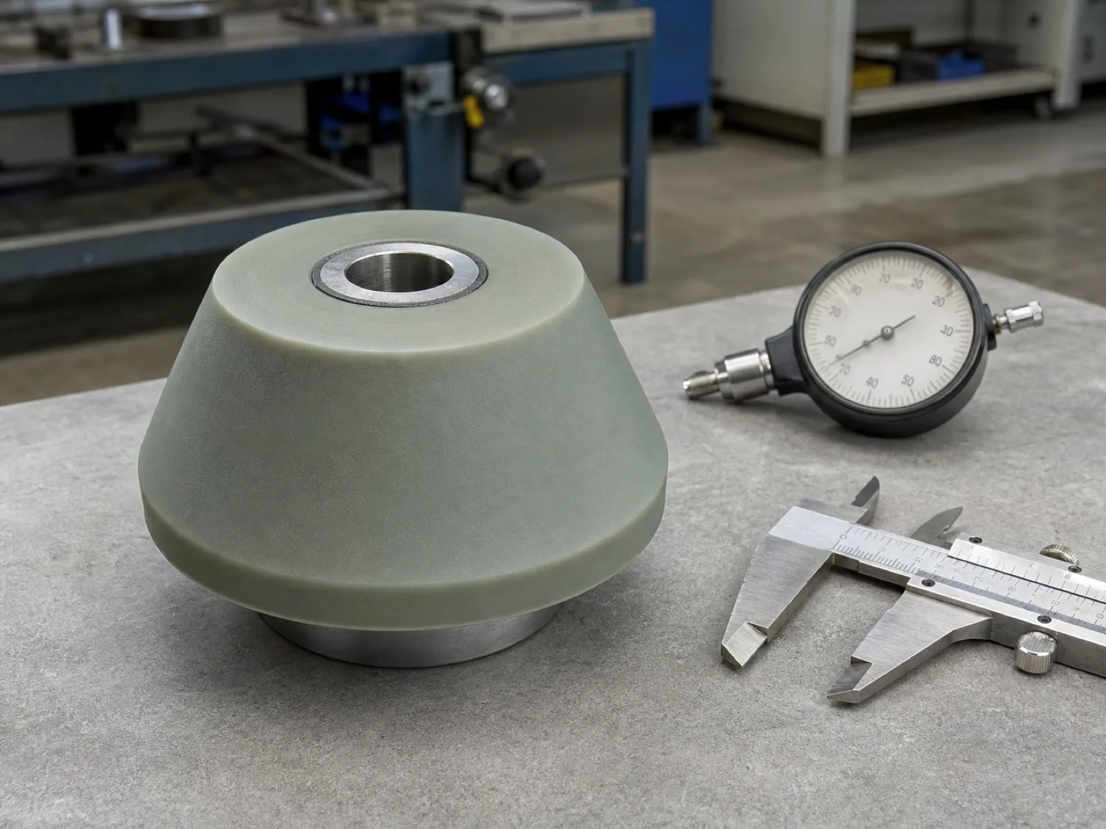
 A silicone engine mount is a rubber-to-metal bonded vibration isolator that uses silicone elastomer instead of natural rubber to carry and damp an engine while surviving high under-hood temperature. Silicone is specified when the mount location exceeds the roughly 100–120 °C ceiling of natural rubber, because it holds -50 °C to 200 °C+ continuous without hardening, cracking, or taking a permanent compression set. Wetop compression- and injection-molds bonded silicone engine mounts in Dongguan at 500-unit OEM MOQ, with per-lot durometer, static-load, and metal-bond data on every shipment.
Sourcing a silicone engine mount is a bonded-assembly problem, not an elastomer-shopping problem. The part is a metal core surrounded by molded silicone, and the durability lives in the bond between the two and in how the durometer and geometry are tuned to the load. This guide is written for OEM and performance-aftermarket buyers specifying engine mounts, motor mounts, transmission mounts, and driveline isolators where heat, service life, or NVH targets push a program off natural rubber. It covers why silicone replaces rubber above rubber’s thermal limit, the temperature envelope, durometer selection by application, how the mount damps vibration and the tensile-versus-damping tradeoff at the heart of the compound, silicone-to-metal bonding, mount geometries, the molding process, and the MOQ, tooling, and validation economics.
What is a silicone engine mount and what does it do?
A silicone engine mount is a bonded rubber-to-metal isolator — a metal core with silicone elastomer molded and bonded around it — that supports the engine's weight, controls its movement under torque and road load, and isolates its vibration from the chassis. Silicone replaces natural rubber when the mount must survive high temperature or a long service life without hardening or sagging.
Every engine mount does three jobs at once, and they pull against each other. It supports the static weight of the engine and transmission. It controls the dynamic movement — the engine wants to rock under acceleration torque, twist under braking, and shake at idle, and the mount limits how far it moves. And it isolates, keeping the engine’s high-frequency vibration and combustion noise from reaching the cabin. A mount that is too soft supports and isolates well but lets the engine move too much; a mount that is too firm controls movement but transmits harshness. The elastomer, durometer, and geometry are the levers that balance the three.
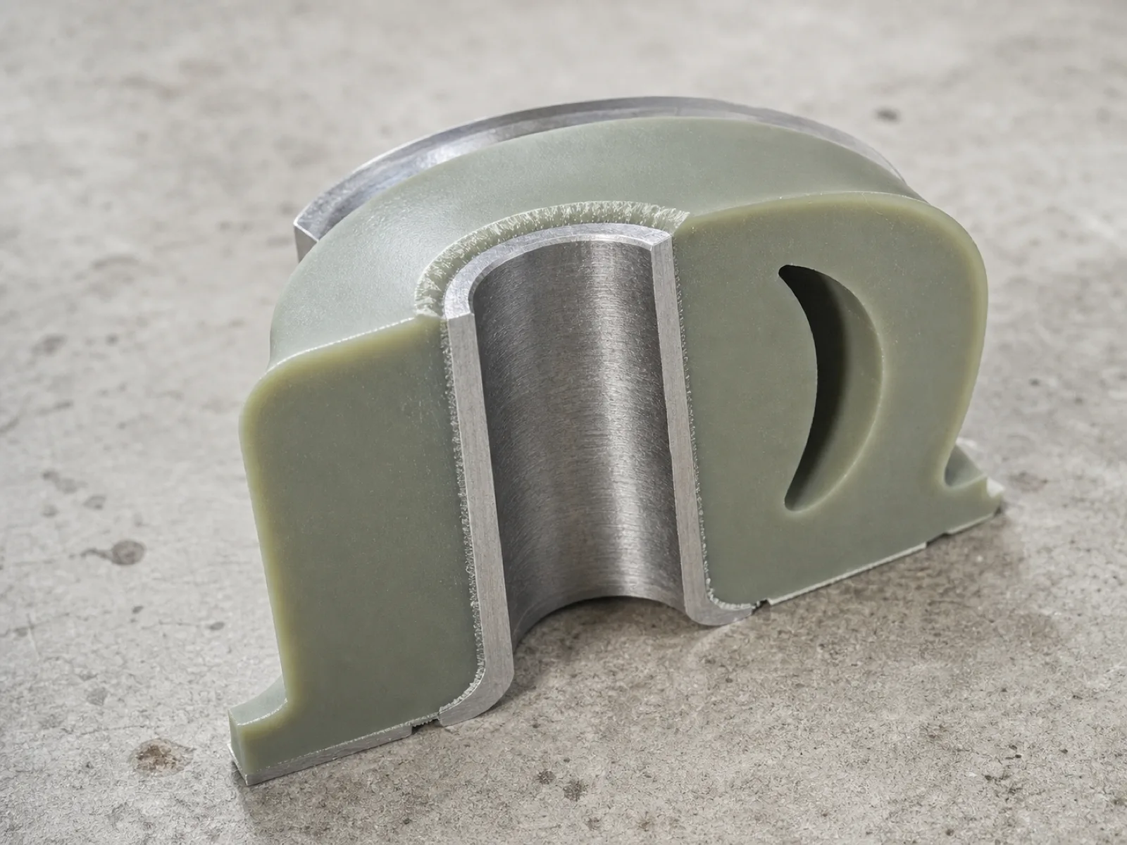
The silicone version of this part is a bonded assembly, not a molded block. At its core is a steel or aluminum insert — a sleeve, stud, or plate that bolts to the engine and the chassis bracket. Silicone is molded around that insert and chemically bonded to it during cure, so the finished mount transfers load through the bond, not through a mechanical clamp. That single fact — the bond is structural — is what separates a real silicone engine mount manufacturer from a shop that molds silicone shapes. If the silicone-to-metal bond fails, the mount fails, regardless of how good the elastomer is.
Silicone is not the default engine-mount material — most volume production mounts are natural rubber, and the highest-isolation OEM mounts are hydraulic (fluid-filled) rubber. Silicone is the specified choice in a defined set of conditions: hot under-hood locations, turbocharged and hybrid drivetrains that run the mount hotter, performance programs that need durometer tuning, and any application where the mount must last the life of the vehicle without the heat-hardening that ends a rubber mount’s service life.
Why does silicone replace natural rubber in an engine mount?
Silicone replaces natural rubber when under-hood temperature exceeds natural rubber's ceiling. Natural rubber begins to harden, crack, and lose damping above roughly 100–120 °C, and it takes a permanent compression set that makes an aged mount sag. Silicone holds -50 °C to 200 °C+ continuous, resists ozone and UV, and does not take that set — so it survives hot engine bays and outlasts rubber.
Natural rubber is an excellent engine-mount material at moderate temperature: it has high tensile strength, high inherent damping, and low cost. Its weakness is heat. Above about 100–120 °C, natural rubber oxidizes, hardens, and cracks; its damping falls, and it takes a growing permanent compression set — the mount physically shrinks and stiffens. In a modern engine bay, where turbochargers, tighter packaging, and downsized engines push under-hood temperatures higher than they were a generation ago, the mount location can sit above that ceiling for hours of continuous operation. A natural-rubber mount in that environment hardens within a few years, transmits more vibration as it stiffens, and eventually cracks.
Silicone solves the thermal problem directly. Its useful continuous range runs from about -50 °C to 200 °C and beyond, it resists ozone and UV that attack natural rubber, and — critically — it holds a very low compression set across that range. A silicone mount does not sag and stiffen with heat cycling the way a rubber mount does, so its isolation stays consistent over the vehicle’s life. The silicone temperature range guide breaks down continuous, intermittent, and peak ratings and how post-cure shifts the ceiling upward.
Silicone’s cost is that it has lower inherent damping than natural rubber and a higher unit price. Neither is a deal-breaker — damping is recovered through compounding and durometer, and the price is justified over the mount’s longer service life — but they are the reason silicone is a deliberate specification for hot and long-life programs rather than a universal upgrade. Where the environment is cool and the design life is short, natural rubber is still the correct, cheaper answer.
What temperature range does a silicone engine mount handle?
A silicone engine mount handles -50 °C to about 200 °C continuous, with short peaks to 230–250 °C, on standard heat-stabilized VMQ compounds. That range covers the full cold-start-to-heat-soak cycle of a turbocharged or tightly-packaged engine bay, where natural rubber's ~100–120 °C ceiling is routinely exceeded. Always specify the continuous operating temperature at the mount location, not the ambient temperature.
Temperature is the reason silicone gets specified, so the envelope matters. Standard silicone (VMQ) for engine mounts is a heat-stabilized grade that holds its mechanical and damping properties across a wide band:
| Rating | Silicone (VMQ) engine mount | Natural rubber engine mount |
|---|---|---|
| Continuous low | -50 °C (special grades -60 °C) | -40 °C |
| Continuous high | 200 °C | ~100–120 °C |
| Short-term peak | 230–250 °C | ~140 °C |
| Compression set at high temp | Very low | High (sags with age) |
| Ozone / UV resistance | Excellent | Poor without antiozonant |
The engineering point buyers miss is the difference between ambient and mount-location temperature. The engine bay’s air temperature might read 90 °C, but the mount bolted next to a turbo manifold or exhaust runner can sit far higher during a heat-soak event after shutdown. Specify the continuous temperature the mount actually sees at its location, not the ambient reading, and confirm whether a quoted peak is a brief heat-soak excursion or a sustained duty. A mount rated for 200 °C continuous and a mount rated for a five-minute 230 °C soak are the same silicone; a mount asked to run 200 °C for hours needs the heat-stabilized grade validated for it.
The cure system also matters at temperature. Platinum-cured silicone tolerates continuous high heat with less reversion and outgassing than peroxide-cured silicone, which is one reason performance and long-life mounts favor it. The platinum-cured vs peroxide-cured guide explains why the cure chemistry, not just the base polymer, sets how a mount behaves after thousands of heat cycles.
What Shore A durometer should a silicone engine mount be?
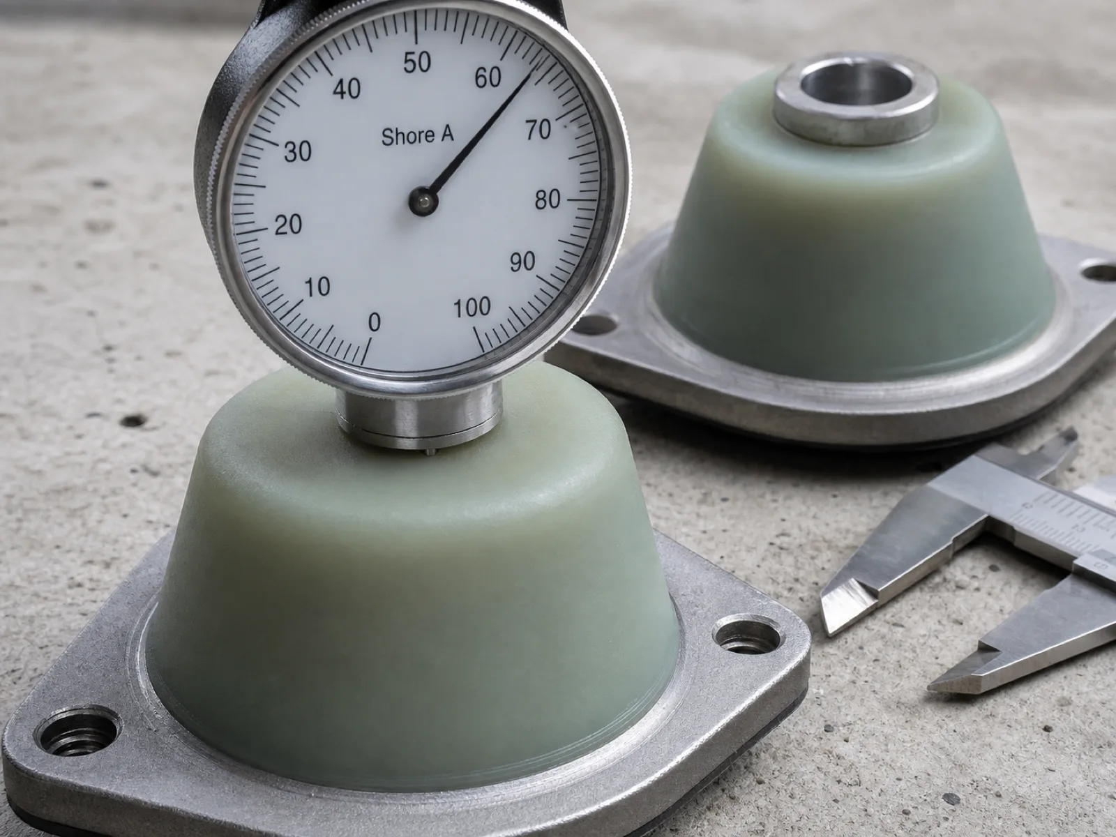
Match durometer to the balance between ride comfort and movement control. Roughly 40 Shore A for comfort-first street mounts, 50 Shore A for OEM-firmness and light towing, 60 Shore A for hybrid daily-plus-spirited duty, and 70 Shore A for drag and high-performance where controlling engine movement beats isolation. Harder durometer transmits more vibration but limits wheel-hop and driveline shock; softer isolates but allows more movement.
Durometer is the primary tuning lever on an engine mount, and it is a direct tradeoff between two things buyers want and cannot have at once: isolation and control. A softer mount isolates vibration and rides smoothly but lets the engine move, which shows up as wheel-hop, torque-steer, driveline shock on shifts, and a vague feel under power. A firmer mount pins the engine in place for crisp response and drivetrain durability but transmits more of the engine’s vibration and harshness into the cabin. There is no free lunch — the right durometer is the one that fits the program’s priority.
| Shore A | Application | Feel & priority |
|---|---|---|
| 40A | Comfort street / OEM-replacement | Maximum NVH isolation, softest ride, most engine movement |
| 50A | OEM-firmness / light towing / daily | Balanced isolation and control, modest movement |
| 60A | Hybrid / daily-plus-spirited / tuned street | Firmer control, noticeable but livable vibration |
| 70A | Drag / track / high-performance | Minimum engine movement, maximum transmitted harshness |
Two notes on using this table. First, the numbers are the silicone body durometer, and they carry a ±5 Shore A manufacturing tolerance that should be written on the drawing and verified per lot under ASTM D2240.1 Second, durometer is not the only stiffness lever — geometry (cone angle, wall thickness, void placement) sets the stiffness ratio between directions, and durometer scales the absolute values. A mount can be made stiff in the load direction and compliant in the isolation direction through geometry, then durometer dials in the overall firmness. For a full breakdown of how Shore A maps to feel and how to read a durometer chart, the Shore A hardness chart covers the scale and its tolerances.
How does a silicone engine mount damp vibration and control NVH?
A silicone engine mount damps vibration through viscoelastic energy dissipation — the elastomer converts a fraction of each vibration cycle into heat — and by tuning its natural frequency below the engine's dominant excitation frequency so it isolates rather than amplifies. Stiffness sets the natural frequency; internal damping absorbs energy at resonance. Softer durometer isolates low frequencies; harder durometer controls large movements.
NVH — noise, vibration, and harshness — is the discipline of keeping the engine’s motion out of the cabin, and the mount is the primary tool. Physically, the mount is a spring and a damper in one part. As a spring, the silicone’s stiffness (set by durometer and geometry) determines the mount’s natural frequency. As a damper, the silicone’s viscoelasticity means it does not return all the energy it stores in each cycle — a portion is dissipated as heat, which is what actually absorbs vibration at resonance.
Isolation theory sets the target: a mount isolates vibration only above roughly 1.4× its natural frequency. So the mount is tuned so its natural frequency sits below the engine’s dominant firing frequency at idle and cruise. Below that frequency the mount transmits vibration; above it, the mount isolates, and the higher the ratio the better the isolation. Softer durometer lowers the natural frequency and widens the isolation band into lower frequencies; firmer durometer raises it, trading isolation for the movement control a performance program needs.
Here is the core silicone engineering tradeoff buyers should understand before selecting a supplier: silicone has high tensile strength and thermal stability but lower inherent damping than natural rubber. Low damping means a silicone mount, left untuned, would ring at resonance more than a rubber one. The compounder addresses this with reinforcing fillers, durometer, and — where needed — a higher-loss compound, raising the loss factor without giving up silicone’s heat resistance. The mount designer addresses it with geometry, placing the resonance away from idle and cruise speeds. A supplier who cannot discuss loss factor and natural frequency is treating your mount as a rubber block, not as a tuned isolator. Dynamic stiffness and loss factor are measured per rubber dynamic-property methods2 on the first article.
Silicone vs natural rubber vs EPDM vs neoprene vs polyurethane
Silicone wins on temperature range, ozone and UV resistance, and service life; natural rubber wins on damping and cost; EPDM wins on weather and coolant resistance; neoprene balances oil and weather resistance moderately; polyurethane wins on stiffness and abrasion for control-focused race mounts. Silicone is the choice for hot, long-life, and NVH-consistent programs — not for cost-floor ones.
Engine-mount elastomers are not interchangeable, and picking the wrong one shows up as a hardened, cracked, or oil-swollen mount in the field. The five candidates, compared on the properties that matter for a mount:
| Property | Silicone (VMQ) | Natural rubber (NR) | EPDM | Neoprene (CR) | Polyurethane (PU) |
|---|---|---|---|---|---|
| Continuous temp high | 200 °C+ | ~100–120 °C | ~150 °C | ~120 °C | ~80–100 °C |
| Continuous temp low | -50 °C | -40 °C | -50 °C | -35 °C | -30 °C |
| Inherent damping | Low–moderate | High | Moderate | Moderate | Low |
| Compression set resistance | Excellent | Poor | Good | Moderate | Moderate |
| Ozone / UV resistance | Excellent | Poor | Excellent | Good | Moderate |
| Oil / fuel resistance | Poor (VMQ) | Poor | Poor | Good | Good |
| Abrasion / tear | Moderate | High | Moderate | High | Excellent |
| Relative unit cost | High | Low | Low–moderate | Moderate | Low–moderate |
The practical reads from this table:
- Silicone is specified for heat and longevity. It runs hotter than any of the others without hardening or setting, and it holds NVH performance over the vehicle’s life. Its weaknesses — lower raw damping and poor oil resistance — are handled by compounding and by not using bare VMQ where the mount sees oil.
- Natural rubber is the volume default: cheap and the best raw damper, but heat-limited and prone to compression set. It is correct for cool, cost-driven mounts.
- EPDM resists weather, ozone, and coolant well and tolerates moderate heat, but it is rarely a primary engine-mount elastomer versus silicone or rubber.
- Neoprene offers a middle ground with usable oil and weather resistance, used where some oil contact is expected.
- Polyurethane is the performance-aftermarket rival: very stiff, tough, and cheap to cast, favored for race mounts that want maximum engine control. It transmits far more harshness than silicone and degrades from heat and hydrolysis over time, so it is a control-first, life-second choice.
Silicone’s advantage is not that it beats every material on every axis — it does not. Its advantage is that it holds its properties across heat and time better than any of the others, which is exactly what a mount in a hot, long-life application needs.
What mount geometries are made in silicone — conical, sandwich, bushing?
The three common isolator geometries are all made in silicone: conical (cone) mounts for compact multi-axis isolation, sandwich or bobbin mounts (silicone bonded between two metal plates) for compression-and-shear duty, and cylindrical bushing mounts (silicone bonded between inner and outer sleeves) for driveline and suspension-style isolation. Geometry sets the stiffness ratio between directions; durometer scales the absolute values.
The mount’s shape does as much tuning as its durometer, because geometry controls how stiff the mount is in each direction independently. The three families cover almost all engine and driveline mounting:
- Conical (cone) mounts — a cone of silicone bonded to a central stud and an outer housing. The cone angle tunes the ratio of radial to axial stiffness, giving multi-axis control in a compact package. Cone mounts are common where the mount must resist load from several directions at once and space is tight.
- Sandwich / bobbin mounts — silicone bonded between two parallel metal plates (sandwich) or as a barrel between two end plates (bobbin). These carry compression load well and shear moderately, and they are simple to bolt in. Used where the primary load is compression with some shear, such as auxiliary and accessory mounts.
- Cylindrical bushing mounts — silicone bonded between an inner metal sleeve and an outer metal sleeve. Bushings give high radial stiffness with tunable torsional compliance, which is why they dominate driveline, sub-frame, and suspension-style isolation. A void or profiled bore tunes the radial-versus-torsional stiffness ratio.
Choosing the geometry starts from the load direction and the required stiffness ratio between directions, not from the durometer. Once the geometry biases the stiffness the right way — stiff where the mount must control movement, compliant where it must isolate — durometer sets the absolute firmness. A supplier who only offers one geometry, or who cannot advise which fits your load case, is selling a shape rather than engineering a mount.
How is silicone bonded to the metal core?
Silicone is bonded to the metal core with a pretreatment-plus-adhesive system applied before insert molding. The metal is degreased, grit-blasted or etched for surface profile, then coated with a two-coat rubber-to-metal bonding agent matched to the silicone cure. The prepared insert is molded into, so the bond forms during vulcanization. Bond strength — verified by peel or push-out test — is the mount's durability-critical variable.
This is the step that makes or breaks a silicone engine mount, and it is where buyers should concentrate their vetting. The silicone-to-metal bond carries the entire load of the mount; if it fails, the silicone can be flawless and the mount still fails. Building a durable bond is a controlled, multi-stage process:
- Surface preparation. The metal insert is degreased to remove oils, then grit-blasted or chemically etched to create a microscopic surface profile the adhesive can key into. A smooth, contaminated insert will not bond, no matter how good the adhesive.
- Bonding-agent application. A two-coat rubber-to-metal bonding system is applied — a primer that keys to the metal and a cover coat that bonds to the silicone — matched to the silicone’s cure chemistry. Platinum- and peroxide-cured silicones need different bonding systems; using the wrong one is a common cause of field delamination.
- Insert molding. The prepared, primed insert is loaded into the mold cavity, and the silicone is molded around it. The bond forms during vulcanization under heat and pressure, so the finished part is one bonded assembly, not a metal core pressed into a silicone sleeve.
- Bond verification. A peel or push-out test on the first article of every run confirms the bond fails in the rubber (cohesive failure), not at the interface (adhesive failure). Interface failure means the pretreatment or adhesive was wrong.
The single most useful question you can ask a prospective supplier is to show their bond-test data. A manufacturer that runs a push-out test on every first article and can explain their pretreatment and adhesive system is engineering the bond. One that talks only about the silicone compound is molding silicone around metal and hoping the bond holds.
How is a custom silicone engine mount molded?
Custom silicone engine mounts are molded by compression, transfer, or injection molding, always with the pretreated metal core insert-molded in place. Compression molding suits low-to-mid volumes and large cores; transfer and liquid-injection molding (LSR) suit higher volumes and tighter tolerances. The process bonds silicone to metal during cure, then a post-cure stabilizes the compound for high-temperature service.
The molding process is chosen from volume, part size, and tolerance, and in every case the metal insert is molded into the part rather than assembled afterward:
- Compression molding — the pretreated insert and a charge of silicone are placed in an open heated mold, which closes and cures under pressure. It handles large metal cores and thick sections well, needs the least tooling investment, and suits the low-to-mid volumes typical of performance and specialty mount programs. This is the workhorse process for bonded silicone mounts.
- Transfer molding — the silicone is forced from a pot through runners into a closed cavity around the insert. It gives better dimensional control and flash management than compression molding and suits mid volumes and more complex cores.
- Liquid injection molding (LSR) — two-part liquid silicone is injected into a closed, heated mold around the insert and cures in a fast automated cycle. It gives the tightest tolerance and the lowest per-unit labor at high volume, at the cost of higher tooling investment. It suits large-run OEM mount programs on smaller cores.
After molding, engine-mount silicone is post-cured — held at elevated temperature for hours — to complete cross-linking, drive off volatiles, and stabilize the compound for continuous high-temperature service. Skipping post-cure leaves a mount that outgasses and drifts in durometer under heat. The silicone molding process guide walks through compression, transfer, and injection molding and where each fits, and the same cell discipline applies whether the mount is one insert or a multi-cavity run.
OEM/ODM workflow, MOQ, tooling, and validation
Wetop's OEM MOQ is 500 units per bonded-mount SKU, with insert-mold tooling of $1,500–4,500 amortized across the first two POs. First-article lead time is 25–35 days including tooling and metal-core pretreatment validation; production runs 30–40 days. A complete RFQ carries the elastomer envelope, metal-core geometry, target durometer, static and dynamic stiffness targets, and the operating temperature range.
The engine-mount OEM workflow runs drawing → tooling → first article → validation → production. What makes it more involved than a plain molded part is the metal core: the insert must be sourced or supplied, pretreated, and validated for bond before production can run.
| Item | Bonded silicone engine mount |
|---|---|
| MOQ per SKU | 500 units |
| Insert-mold tooling | $1,500–4,500 (core complexity, cavity count) |
| First-article lead time | 25–35 days (incl. tooling + bond validation) |
| Production lead time | 30–40 days |
| Metal core | Customer-supplied or Wetop-sourced (adds 5–10 days) |
| Durometer split on same tool | Combines toward compound minimum |
| Pantone / color match | +$0.10–0.25 / unit (rarely needed on mounts) |
A complete engine-mount drawing carries more than a molded-part drawing does, because the mount is a tuned assembly:
- Elastomer envelope — the outer silicone geometry with tolerances.
- Metal-core geometry — insert drawing, material, and whether the customer supplies it or Wetop sources it.
- Target durometer — Shore A with a ±5 tolerance.
- Static stiffness — the spring rate (load-deflection) in each loaded direction.
- Dynamic stiffness and loss factor — at the operating frequency, if the program has an NVH target.
- Operating temperature — continuous, at the mount location.
- Validation requirement — static load, dynamic property, bond push-out, and fatigue cycle count.
Validation is where a real manufacturer proves the mount. The first-article report should cover static load-deflection (spring rate matches the drawing), dynamic stiffness and loss factor per rubber dynamic-property methods,2 a metal-to-silicone bond push-out or peel test, and a cyclic fatigue test to the target life. Compression set is checked to predict long-term sag,3 and the elastomer is classified to the automotive line-callout system where the drawing calls for it.4 For the full economics of MOQ, tooling amortization, and lead time across silicone OEM programs, the MOQ and lead time guide breaks down how tooling cost spreads across the first two production orders.
How to vet a silicone engine mount manufacturer
Vet a silicone engine mount manufacturer against six checkpoints: in-house insert molding with metal-core pretreatment, documented rubber-to-metal bond testing, dynamic stiffness and loss-factor measurement capability, durometer and static-load QC per lot, fatigue-test validation, and an open plant audit. A supplier who cannot show bond-test and dynamic-property data is molding silicone around metal, not engineering a bonded isolator.
The vetting checklist for a first-time engine-mount supplier:
- Confirm in-house insert molding and metal pretreatment. The bond is structural, so the supplier must degrease, blast or etch, and prime the metal core in-house under a controlled process — not subcontract it. Ask to see the pretreatment line.
- Ask for rubber-to-metal bond-test data. A real manufacturer runs a peel or push-out test on first articles and can show the bond fails cohesively in the rubber. If they cannot explain their bonding system by cure chemistry, they are guessing at the most failure-prone step.
- Confirm dynamic-property measurement capability. The mount is a tuned isolator; the supplier should measure dynamic stiffness and loss factor, not just static hardness. A shop that only reports durometer is treating your mount as a block.
- Verify per-lot durometer and static-load QC. Every production lot should carry durometer under ASTM D2240 and a static load-deflection check against the drawing spring rate.
- Ask about fatigue validation. The supplier should be able to cycle a mount to a target life and report whether it delaminates or cracks — the durability proof buyers most often skip.
- Ask if they welcome a plant audit. A supplier who resists a factory visit is usually hiding a subcontracted bonding step or a rented facility. An open audit invitation is the strongest signal of a genuine manufacturer.
Run this checklist before the first PO, not after the first field failure. A bond or fatigue failure on a shipped engine-mount program carries warranty and safety exposure far beyond the cost of a document review and a plant visit under an ISO 9001 quality system.5
FAQ
For frequently asked technical questions on durometer selection, temperature limits, silicone-to-metal bonding, NVH and vibration damping, geometry, MOQ, and fatigue validation, see the FAQ list in the frontmatter block — the same questions render on the deployed page and feed the FAQ schema.
Sourcing custom silicone engine mounts — next step
Wetop manufactures bonded silicone engine mounts — conical, sandwich, and bushing geometries — from a 7,500 m² factory in Dongguan, 90 minutes from Yantian Port. Insert molding, metal-core pretreatment, and rubber-to-metal bonding run under one ISO 9001 quality system, with 40–70 Shore A durometer tuning, heat-stabilized VMQ to 200 °C+, and per-lot durometer, static-load, dynamic-property, and bond-test data on every shipment. For an RFQ with a drawing carrying the elastomer envelope, metal-core geometry, target durometer, stiffness targets, and operating temperature, talk to the engineering desk.
Footnotes
-
ASTM D2240 durometer hardness standard. ASTM International. See references. ↩
-
ISO 4664 rubber dynamic-property determination. See references. ↩ ↩2
-
ASTM D395 rubber compression-set test methods. ASTM International. See references. ↩
-
ASTM D2000 rubber classification for automotive applications. ASTM International. See references. ↩
-
ISO 9001:2015 Quality Management Systems. See references. ↩
FAQ
-
Are silicone engine mounts better than rubber engine mounts?
Silicone engine mounts are better where heat, ozone, and service life matter; standard rubber mounts are cheaper and damp vibration slightly better at ambient temperature. Natural rubber softens and cracks above roughly 100–120 °C, while silicone holds its properties from -50 °C to 200 °C+ without hardening or taking a permanent compression set. That makes silicone the right choice for hot under-hood environments, turbocharged and hybrid drivetrains, and programs that need the mount to outlast the vehicle. For a cost-driven mount in a cool, low-vibration application, natural rubber is still the economical answer. The decision is thermal environment and design life, not a blanket 'silicone is superior' claim.
-
What Shore A durometer should a silicone engine mount be?
Match durometer to how much movement control the application needs versus ride comfort. Roughly: 40 Shore A for street mounts prioritizing NVH isolation and ride comfort, 50 Shore A for OEM-firmness and light towing, 60 Shore A for hybrid daily-plus-spirited duty, and 70 Shore A for drag racing and high-performance where minimizing engine movement under load beats isolation. Harder durometer transmits more vibration but controls wheel-hop, torque-steer, and driveline shock; softer durometer isolates better but allows more engine movement. Most performance aftermarket mounts land at 60–70 Shore A; OEM comfort mounts sit at 40–55 Shore A. Specify durometer with a ±5 tolerance on the drawing.
-
Can silicone replace natural rubber in a high-temperature engine mount?
Yes — high under-hood temperature is the single most common reason to switch an engine mount from natural rubber to silicone. Natural rubber begins to harden, crack, and lose damping above about 100–120 °C, and modern turbocharged and tightly-packaged engine bays routinely run hotter than that at the mount location. Silicone holds -50 °C to 200 °C+ continuous, resists ozone and UV that attack natural rubber, and does not take the permanent compression set that makes an aged rubber mount sag and transmit vibration. The tradeoff is that silicone has lower inherent damping and higher unit cost, both of which are addressed through compounding and durometer selection rather than being deal-breakers.
-
How is silicone bonded to the metal core of an engine mount?
Silicone is bonded to the metal core through a pretreatment-plus-adhesive system applied before insert molding. The metal insert is degreased, then grit-blasted or chemically etched to create surface profile, then coated with a two-coat rubber-to-metal bonding agent (a primer and a cover coat) matched to the silicone cure system. The prepared insert is loaded into the mold cavity and the silicone is compression- or injection-molded around it, so the bond forms during vulcanization. Bond integrity is the durability-critical variable in an engine mount — a peel or push-out test on the first article of every run verifies it. A supplier that cannot show bond-test data is molding silicone around metal and hoping, not engineering a bonded assembly.
-
What is the difference between a silicone and a polyurethane engine mount?
Polyurethane mounts are firmer, transmit more noise and vibration, and are favored in motorsport for maximum engine control; silicone mounts hold a far wider temperature range and last longer without hardening. Polyurethane has excellent tear and abrasion resistance and is inexpensive to cast, but it degrades from heat, hydrolysis, and UV over time and transmits harshness that most street drivers dislike. Silicone runs -50 °C to 200 °C+, resists heat and ozone, and can be tuned soft for comfort or firm for control through durometer. For a hot, high-mileage, or comfort-sensitive program silicone is the durable choice; for a cost-driven, control-only race mount polyurethane competes. They solve different priorities.
-
How does a silicone engine mount reduce vibration and noise (NVH)?
A silicone engine mount reduces NVH by converting engine vibration into a small amount of heat through the elastomer's viscoelastic energy dissipation, and by placing its natural frequency below the engine's dominant excitation frequency so it isolates rather than amplifies. The mount acts as a spring-and-damper: the silicone's stiffness sets the natural frequency, and its internal damping absorbs energy at resonance. Softer durometer lowers the natural frequency and isolates more low-frequency vibration; harder durometer raises it and controls large engine movements. Because silicone has lower inherent damping than natural rubber, the compound is tuned with fillers and durometer, and geometry is designed so the mount's resonance sits away from idle and cruise engine speeds.
-
What is the MOQ and lead time for custom silicone engine mounts?
Wetop's OEM MOQ is 500 units per bonded-mount SKU — one specific geometry, durometer, and metal core on its own insert-mold tool. Insert-mold tooling runs $1,500–4,500 depending on core complexity and cavity count, and amortizes across the first two production orders. First-article lead time is 25–35 days including tooling and metal-core pretreatment validation; production lead time is 30–40 days. Send a drawing with the elastomer envelope, metal-core geometry, target durometer, static and dynamic stiffness targets, and the temperature range to quote. Split-durometer runs on the same geometry combine toward the compound minimum.
-
What mount geometries can be made in silicone — conical, sandwich, bushing?
All three common isolator geometries are made in silicone: conical (cone) mounts for compact multi-axis isolation, sandwich or bobbin mounts (silicone bonded between two parallel metal plates) for shear-and-compression duty, and cylindrical bushing mounts (silicone bonded between an inner and outer metal sleeve) for suspension-style and driveline isolation. Each geometry biases stiffness differently: conical mounts tune radial versus axial stiffness through cone angle, sandwich mounts carry compression well and shear moderately, and bushing mounts give high radial stiffness with controlled torsional compliance. The geometry is chosen from the load direction and the required stiffness ratio, then the durometer fine-tunes the absolute values.
-
How are silicone engine mounts validated for durability and fatigue?
Silicone engine mounts are validated with a combination of static load-deflection testing, dynamic stiffness and damping measurement, metal-to-silicone bond testing, and cyclic fatigue testing to a target cycle count under representative load. Static testing confirms the spring rate matches the drawing; dynamic testing per rubber dynamic-property methods confirms the stiffness and loss factor at operating frequency; bond push-out or peel testing confirms the insert adhesion; and fatigue testing cycles the mount to failure or to a validated life to confirm it will not delaminate or crack in service. A competent manufacturer issues a first-article report covering all four and repeats load and durometer checks per production lot.
-
Why do silicone engine mounts cost more than rubber, and is it worth it?
Silicone engine mounts cost more because the base polymer is more expensive than natural rubber, the metal-to-silicone bonding system is more demanding, and platinum-cured or heat-stabilized grades add cost. Whether it is worth it is a cost-of-ownership question: a silicone mount that survives a hot under-hood environment for the life of the vehicle can be cheaper over time than a rubber mount that hardens, sags, and gets replaced twice. For hot, high-mileage, warranty-sensitive, or performance programs the longevity offsets the higher unit price. For a cool, low-mileage, cost-floor application it does not, and natural rubber is the correct economic choice.
References
Authoritative sources cited in this guide
- International Organization for Standardization. ISO 9001:2015 — Quality Management Systems — Requirements. https://www.iso.org/standard/62085.html — The documented quality system Wetop's engine-mount production discipline is certified against.
- ASTM International. ASTM D2000 — Standard Classification System for Rubber Products in Automotive Applications. https://www.astm.org/products-services/standards-and-publications/standards.html — The line-callout system automotive drawings use to specify an elastomer, including silicone (type/class), for mount rubber.
- ASTM International. ASTM D2240 — Standard Test Method for Rubber Property — Durometer Hardness. https://www.astm.org/d2240-15r21.html — Defines the Shore A durometer method Wetop reports on every engine-mount lot.
- ASTM International. ASTM D395 — Standard Test Methods for Rubber Property — Compression Set. https://www.astm.org/products-services/standards-and-publications/standards.html — The compression-set test that predicts whether a mount will sag and lose isolation over its service life.
- SAE International. SAE Ground Vehicle Standards — Elastomer and NVH. https://www.sae.org/standards/ — Automotive elastomer, vibration, and NVH standards a mount program's dynamic requirements are written against.
- International Organization for Standardization. ISO 4664 — Rubber, vulcanized or thermoplastic — Determination of dynamic properties. https://www.iso.org/standards.html — The dynamic stiffness and loss-factor method used to characterize a mount's damping at operating frequency.
- European Chemicals Agency (ECHA) — EUR-Lex. REACH Regulation (EC) No 1907/2006 — SVHC candidate list. https://eur-lex.europa.eu/legal-content/EN/TXT/?uri=CELEX%3A32006R1907 — Substance-of-very-high-concern screening applied to mount compounds shipped into the EU.
Start a custom program
Send a brief. Get an engineer’s reply in one business day.
Every Wetop program is tooled from a customer’s specification. Send a CAD file (STEP · IGES · DWG) or a written brief and we’ll reply with a mold cost estimate, price brackets at MOQ 500 / 1,000 / 5,000, and any engineering questions.